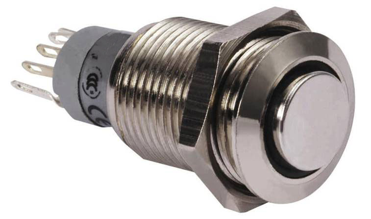
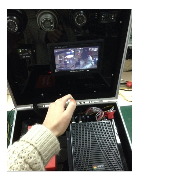
MV Secure Drive SOS Panic Button (MV-SD-ACC-SOS)
To connect thetwo wires of the panic button to the two wires (SENSOR IN1 and 12V) from the 24pin I/O cablesof MDVR. Defaulted high voltage trigger is 12V /5V.
Complete Product Details
To connect thetwo wires of the panic button to the two wires (SENSOR IN1 and 12V) from the 24pin I/O cablesof MDVR. Defaulted high voltage trigger is 12V /5V.
SENSOR IN1 and 12V-OUT is for panic button alarm input out of the MDVR 24pin I/O cables.
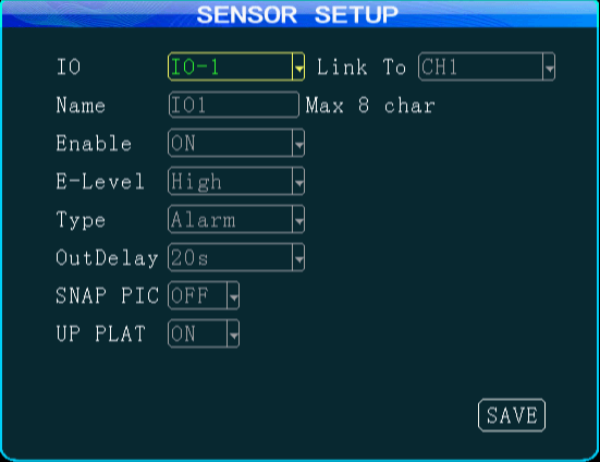
Enter the menu ¾ Alarm ¾ Sensor ¾ enable the IO-1 option
It uses the high voltage trigger to linkage the camera channel to enable real-time video pop-out when alarm triggered.
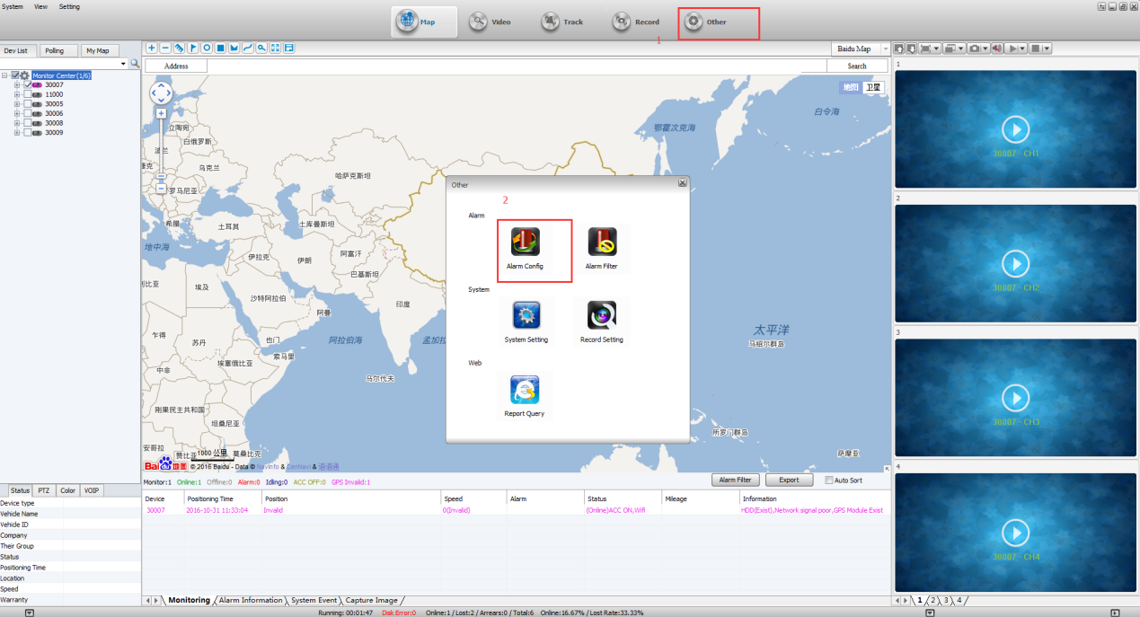
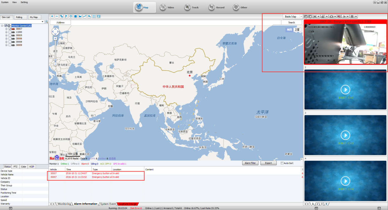
Login IVMS clientsoftware, click the Other ¾alarm Config
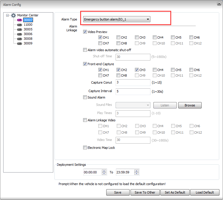
On the Alarm Config page, choose the Alarm Type the emergency button alarm/IO_1 then save it.
When the driver presses the panic button, the alarm will be triggered, and sent to the server from the MDVR via 3G /4G. It will pop out a real-time video on the IVMS Client software at the same time.
There are other alarm type optional according to different type of alarm applications, please consult with our technical team for further information.
Thank you.
Type: PDF Size: 613 KB Downloads: 5
- Metal button
- Real-time video pop-out and snap-shot by alarm linkage
- to generate alarm reports for search and download